pakembaran
desa pakembaran adalah desa yang berjarak 4 km dari kecamatan yang berada di kabupaten pemalang penduduk di desa pakembaran sekitar 7000 jiwa rata rata dari mereka memiliki pekerjaan sebagai petani dan ada juga yang merantau
di desa pakembaran terdapat dusun dimana saya tingal dusun itu bernama bungbas konon katanya nama ini di ambil karna di situ ada kali yang bernama kali rambut dan terdapan kedung bungbas dan bukuit yang bernama bungbas nah itu awalnya kata bungbas tapi ada pendapat lain yang mengatakan bahwa bungbas itu adalah nama jalan yang berada di rt 06 dan rt 07 di situ lah para remaja dan anak-anak membuat kelompoknya masing masing dan tak pernah berhenti sejak dulu dari generasi yang satu ke generasi yang lain
dan di desa pakembaran terdapat sekolah sd n 1 pakem baran yang berada di rt 8 rw 2 di situ banyak yang sudah menjadi alumi tetapi mereka tetap menjadi keluarga besar dan setiap tahun biasanya mereka mengadakan reoni yang di lakukan oleh gene rasi yang sudah berumur 1 s/d 5 generasi tapi di lakukan secara bergantian
dan ada juga sd n 02 yang berada di sebelah selatan desa pakembaran di sana juga sudah melahirkan banyak alumi dulu sd 1 sama sd2 itu berdekatan setelah mengalami refolusi mereka ber pisa menjadi sangat jauh
nah pakembaran ini lah tempat tinggal ku semoga bermanfaat
Selasa, 29 November 2016
gelempang binangun karanggayam
rutina arisan ibu rumah tangga di desa binanggun

karanggayam tepatnya di desa binangun terdapat kebiasaan ibu-ibu rumah tangga yaitu arisan rutinan setiap hari minggu manis yang berada di kantor kelurahan binangun yang di ikuti oleh warga sekitar dan yang mendapat arisan bisa membawa pulang uwang sebesar Rp 600.000

dan apabila seseorang yang tidak berangkat maka biasanya mereka hanya titip untuk mengisi arisan saja karna adat di desa binangun masih terbilang kental maka disana kebanyakan orang masih memelihara hewan ternak seperti kambing,kerbau,sapi dan lain lain
 di desa binangun juga terdapat sd n 01 yang biasa untuk sekolah anak-anak binangun

karanggayam tepatnya di desa binangun terdapat kebiasaan ibu-ibu rumah tangga yaitu arisan rutinan setiap hari minggu manis yang berada di kantor kelurahan binangun yang di ikuti oleh warga sekitar dan yang mendapat arisan bisa membawa pulang uwang sebesar Rp 600.000

dan apabila seseorang yang tidak berangkat maka biasanya mereka hanya titip untuk mengisi arisan saja karna adat di desa binangun masih terbilang kental maka disana kebanyakan orang masih memelihara hewan ternak seperti kambing,kerbau,sapi dan lain lain

Senin, 21 November 2016
wisata di karanggayam
Mengenal Curug Kedondong di Desa Gunungsari
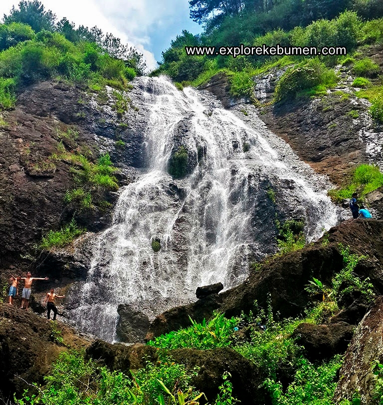
Curug Kedondong (Photo: http://www.explorekebumen.com)
Curug Kedondong memiliki suasana alam yang masih sangat alami. Maklum saja, curug ini belum terjamah manusia luar kecuali warga desa setempat. Curug ini berada di batas hutan pinus dengan hutan garapan warga. Jadi, sumber air dari Curug Kedondong merupakan dari aliran sungai di sela sela hutan pinus diatasnya. Sungai yang berarah Barat ke timur tersebut berasal dari bukit bukit di bagian hulunya seperti Bukit Igir Kunir, Bukit Igir Gepuk dan Bukit Batok. Nah, Curug Kedondong berada di bagian timur dari Bukit Batok.
Curug Kedondong tidak memiliki kolam untuk berenang ataupun berendam. Hal tersebut karena dibawah curug hanya terdiri dari bongkahan bongkahan batu. Curug Kedondong juga tidak banyak dikelilingi pohon rindang sehingga akan cukup panas jika harus berlama lama dibawah air terjun saat cuaca panas terik. Namun tak perlu risau, pengunjung tetap bisa berteduh di pohon-pohon dan gubuk yang tak jauh dari curug.
Curug Kedondong bukalah tempat wisata yang dikelola. Bagi pengunjung yang ingin melihat dan merasakan kesegaran air serta pemandangannya harus rela berjalan kaki dan bersusah payah terlebih dahulu. Untuk menuju ke lokasi ini Lintas Kebumen mencoba untuk memberikan rutenya:
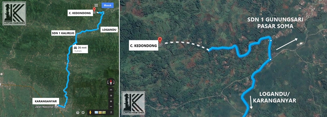
Klik untuk memperbesar.
sumber;https://lintaskebumen.wordpress.com/2015/01/28/mengenal-curug-kedondong-di-desa-gunungsari/
Gemerujug Curug Sikebut
16.30
|
| Curug Sikebut, Karanggayam |

“Alam utara Kebumen tiada habisnya menyimpan permata!”. Itulah yang saya percayai selama ini karena memang belum banyak orang yang mengungkap pesona di daerah Kebumen utara. Jauh dan terpelosok menjadi alasan orang malas untuk menyambangi. Kabar yang samar tentang sebuah air terjun di kawasan Kecamatan Karanggayam, daerah Kebumen Utara, lantas menggerakkan saya bersama sahabat saya, Anas, untuk menjelajah ke sana.
“Dik, tahu Curug Sikebut? Masih jauh curug nya?” tanya saya dalam bahasa
Jawa Ngapak pada bocah yang kebetulan melintas tatkala tiba di Desa Ginandong,
Karanggayam.
“Tahu mas. Masih lumayan jauh. Satu km lagi” jawabnya.
“Bisa jalan ke curugnya?"
“Teyeng” jawabnya singkat dengan
keluguannya
Haaah.. sudah lama saya tak dengar kata ‘teyeng’. Sengaja saya tidak menerjemahkan pada bahasa Indonesia
karena saya begitu tergelitik dengan kata ini. ‘Teyeng’ arti bebasnya adalah ‘bisa’. Terakhir saya dengar kata ‘teyeng’ semasa SMA dulu, tujuh tahun lalu. Masih
adanya kata ‘teyeng’ ini bisa
mengindikasikan bahwa desa ini masih jauh menyepi dari hiruk pikuk keramaian
modernitas.
Lantas, pada rumah penduduk di sebuah pertigaan, saya minta izin
menitipkan motor sekaligus meminta
petunjuk ke Curug Sikebut. Dari rumah itu, Sikebut sudah tampak di
seberang sana, di dalam hutan yang dilingkupi pepohonan pinus. Saya rasa akan
dekat saja kami berjalan kaki. Tidak butuh lama untuk menjangkaunya.
“Ya palingan setengah jam sampai sejam jalan kaki dari sini. Nanti melintasi
dua sungai.” ucap ibu pemilik rumah.
Mendung menggelayut makin kecut. Kami pun bergegas untuk lekas menemui
Sikebut. Tadinya kami meragu, takut di tengah perjalanan hujan deras
mengguyur. Tapi, kami sudah datang jauh
dan terpelosok sampai di Ginandong, dari pusat kota Kebumen saja sekitar 30 km
ke utara melewati jejalanan yang di beberapa titik rusak parah. Kami pun putuskan untuk melanjut.

|
| Alam Kebumen utara di daerah Karanggayam. Banyak ditemui terasering yang eksotis. |


|
| Sungai yang mengiringi perjalanan kami. Sejuk dipandang mata. |


|
| Curug Ginandong. Curug yang menawan, ditemui saat perjalanan ke Sikebut lewat jalur bawah. |

Beruntung kami berjumpa dengan seorang bapak di tengah jalan. Dia akan pergi
mengurus ladangnya di tengah hutan tak jauh dari Sikebut. Kami pun berturut
jalan bersamanya, membelah pekuburan, melintasi ladang hingga tiba di sebuah
sungai. Atas sarannya, saya dan Anas diminta ke kiri, menyisir sungai. Kata
dia, lebih mengasyikkan karena ditemui beberapa
curug lain dalam perjalanan ke Sikebut. Yang paling menarik nanti adalah
Curug Ginandong. Bapak itu ke kanan. Kami pun berpisah.
Sekarang hanya kami berdua, dua lelaki yang senang bertamasya, alih-alih
berpetualang, untuk menemukan tempat-tempat indah di Kebumen, kampung halaman
kami yang begitu melimpah potensi tapi sedikit yang peduli menggali, apalagi
pemerintah daerah Kebumen itu sendiri. Ciih… ‘Ngrasani’ pemerintah kami sudah
lelah, sehingga lebih baik terjun beraksi.
Dari tadi menikmati sejuk suasana perjalanan yang dikawani gemericik
sungai, akhirnya kami mendengarkan suara gemerujug. Sempat juga sekedar menatap
dari semak-semak suatu rambatan air dari ketinggian. Aha.. kami menyambut
semangat. Curug Ginandong pun terpandang begitu anggun dengan ketinggian yang
tak terlalu semampai. Curug ini merupakan jatuhnya aliran sungai yang merayapi tebing
dengan perlahan. Tingginya paling hanya sekitar 12 meter. Suasana sekitar
begitu meromantika dengan hijaunya ladang warga dan rerumputan liar. Sejenak
kami pun memesrai panorama sekaligus merehat sekejap. Kami hanya memandang dari
ketinggian, tiada gairah untuk turun ke bawah, apalagi jalan menjangkaunya teramat
susah.
Perjalanan berlanjut. Kini kami berpisah dengan sungai. Mengitari bukit
lalu berjumpa lagi dengan sungai yang lain. Samar-samar Sikebut sudah terlihat.
Seorang ibu pencari rumput tampak sedang beristirahat. Kami menyapanya
sekaligus bertanya. “Lewat mana Bu kalau ke curug?”. Ah, ternyata jalan yang
kami lalui ini salah. Kami harus mendaki lereng curam yang berhiaskan pepohonan
pinus untuk menuju setapak tanah yang benar. Semak belukar pun mau tidak mau
harus kami terjang. Saya agak terhambat dengan sandal jepit saya yang melicin.
Anas lancar-lancar saja karena ia beralas sepatu khas penjelajah.
Suara gemerujug Sikebut kian riuh. Artinya kami makin mendekat. Kini
jalanan tidak lagi terjal karena sudah
berada di jalan yang benar. Tak sampai 5
menit kemudian, kami sudah berada di kaki Curug Sikebut. Sang permata pun telah
didapatkan! Voila….
Bercucuran air jatuh pada tebing setinggi 30 meter. Bebatuan besar di
bawahnya tak gentar untuk menyambut. Saya di tepinya merasakan
percikan-percikan air berpadu dengan sapuan angin dari seberang pandang. Saya
duduk menikmati suasana sembari membinasakan lelah. Anas duduk di samping saya
sambil berkisah tentang struktur batuan pada tebing Sikebut. Dia jelaskan bahwa
ada tiga lapisan batuan, yakni beku, sedimen lalu beku lagi sehingga dapat
digambarkan proses terbentuknya kawasan ini selama ribuan bahkan jutaan tahun
lalu.
Curug Sikebut menjadi permata yang
jarang terjamah oleh khalayak ramai manusia. Belum banyak yang mengetahuinya.
Dilingkupi nyaman oleh paduan hutan pinus milik Perhutani dengan kawasan ladang
penduduk setempat. Sikebut tenang mengucur sejak silam tak mati oleh gerusan
zaman. Debit air yang stabil meski di musim hujan menjadi pertanda bahwa
lingkungan di sana masih lestari.

|
| Menembus semak untuk menuju setapak yang benar. |


|
| Curug Sikebut dari dekat. Menikmati percikan air. Segaaar.. |


|
| Polos dan tanpa ragu meloncat ke kubangan air. Byuuuuur... |

Ah, tapi sayang. Walau baru sedikit saja manusia yang datang ke Sikebut, sampah telah ada mengotor di mana-mana. Sedih. Selalu saja, kesadaran pewisata lokal masih kurang untuk menjaga kebersihan di tempat yang indah ini. Anas dan saya pun memulungi sampah untuk dibawa keluar dari kawasan Sikebut. Jaga kebersihan dong!
Sore mulai menanti sehingga kami pun beranjak pergi. Kami berencana pulang
melalui jalur berbeda, yakni jalur atas. Tadi kami berangkat melalui jalur
bawah karena untuk menjemput Sikebut tepat di bawah gemerujug airnya. Jalur
atas ini untuk meromantika Sikebut dari atas igir-igir bukit. Aha.. Kami
berjumpa dengan bocah-bocah yang sedang mandi di sebuah kolam tempat jatuhnya
rayapan air di atas bebatuan. Dan, mereka telanjang!
Bukannya takut ketika akan dipotret, mereka malah bangga dengan
ketelanjangannya. Berkali-kali mereka bergaya. Berkali-kali juga mereka lompat
dari sebuah batuan ke air. Byuuuuuur… Untungnya semua laki-laki. Hanya satu
bocah yang mengenakan celana ketika mandi di kubangan. Bocah-bocah yang seusia
kelas 1 dan 2 SD ini sedang menunggui paman salah satu bocah itu mengambil
rumput di ladang. Saya dan Anas berucap salut dengan keberanian mereka
untuk tetap polos, lugu dan telanjang.
Ah, bocah-bocah desa ini begitu menyenangkan tapi menggelikan.
Kami mesti mendaki lereng berumput untuk naik menuju Jalur Atas. Tidak
begitu susah, tapi kami mesti berhati-hati. Sesampai di atas, terlihatlah lebih
lapang Curug Sikebut dan sekitarnya. Saya makin mencinta pada panorama kawasan
Sikebut. Ada kedamaian terasa. Ada kepuasan atas imaji yang indah tiada tara.
Di seberangnya, perbukitan Serayu Selatan yang menjadi pembatas Kebumen dan
Banjarnegara terlihat melekuk-lekuk, melapis-lapis. Bukankah ini panorama yang
pantas atas jerih payah menjangkau daerah ini!
***
Perjalanan pulang kami dipandu dengan hati riang sehingga tak terasa kami
sudah tiba di rumah warga tempat motor kami diparkir. Jujur, tadi sempat
‘blushuk’ salah jalan sehingga
perjalanan pulang ini lebih lama.

|
| Panorama pegunungan Serayu Selatan yang membatas Kebumen dan Banjarnegara |


|
| Air merayapi batuan. Segar. Ditemui menjelang Curug Sikebut. |

 |
| Seorang warga yang saya temui di ladang, memanen dan mencari rumput untuk ternaknya. |
“Wah, maeeeen gambare (bagus
gambarnya). Sikebut kelihatan juga gambarnya “ ungkap penuh keterkejutan dari
Ibu sang pemilik rumah ketika meminta saya untuk membuktikan foto kalau saya sudah sampai di Curug Sikebut. Dia tadinya
tak yakin bahwa kami sampai di Curug Sikebut mengingat medannya tak mudah.
Tapi, tak hanya itu maksud Ibu mengecek foto Curug Sikebut saya. Dia berkisah bahwa ada seseorang mencoba
memotret Curug Sikebut tapi tidak bisa. Gambarnya tidak terlihat, menghitam
semuanya. Ah, mendengar kisah itu lalu saya coba mematikan kamera lalu
menghidupkan lagi. “Tetap saja ada kok Bu fotonya.”
“Wah berarti masnya ini orang pintar.” jawabnya dengan polos. Saya sengaja
tak menanyakan maksud pintar ini dalam hal apa. Apakah ‘orang pintar’ atau
pintar dalam artian sebenarnya. Saya berpikiran bisa saja memang kameranya itu
salah pengaturan atau juga malah kamera jadul yang tak memiliki layar untuk
melihat langsung jepretan. Ah, biarlah apa anggapnya mereka jikalau bagus untuk
kelestarian Sikebut.
Curug Sikebut bagi orang setempat dianggap sebagai tempat keramat. Oleh
karena itu, tak banyak penduduk yang sering datang ke sana. Ibu itu terakhir ke
Sikebut dua tahun lalu meski rumahnya begitu dekat. Kemudian, dia mengisahkan
pernah ada kejadian tak senonoh alias dari muda-mudi di Curug Sikebut, pasangan
itu lantas kena azab. Sampai-sampai untuk mengatasinya perlu didatangkan Tetua
setempat. Saya tak perlu ceritakan bagaimana kejadiannya karena perbuatan ini
sepatutnya hanya boleh dilakukan suami-istri.
Silakan percaya atau tidak! Tapi bagi saya, ini adalah sebuah pesan luhur bahwa
menjaga moral di tempat wisata adalah sebuah keniscayaan, sebuah keharusan.
Curug Sikebut yang indah bagaikan permata tak boleh dicemari oleh perbuatan
amoral dari pengunjung oportunis yang tak bertanggungjawab. Silakan nikmati
keindahannya yang sunyi, tapi jangan berbuat maksiat keji!
 |
| Curug Sikebut dilihat dari jalur atas bukit. |
 |
| Sahabat saya yang selalu riang bergembira sepanjang perjalanan |
 |
| Ayoook Dik, foto dulu!! Pose mereka menantang!! |
 |
| Aktivitas 'nglukhu' di persawahan Karanggayam. Masih tradisional tapi inilah yang paling efektif untuk sawah berbukit |

|
| Di sawah-sawah Karanggayam masih banyak ditemui potret warga mengumpulkan rerumputan untuk ternaknya. |

 |
| Curug Sikebut |
  |
| Curug kecil yang banyak ditemui di sekitar Curug Sikebut. |
karanggayam
Karanggayam, Kebumen
Dari Wikipedia bahasa Indonesia, ensiklopedia bebas

-
 Untuk kegunaan lain dari Karanggayam, lihat Karanggayam (disambiguasi).
| Karanggayam | |
|---|---|
| Kecamatan | |
 Kantor Camat Karanggayam |
|
| Negara | |
| Provinsi | Jawa Tengah |
| Kabupaten | Kebumen |
| Luas | 148,4 km² |
| Jumlah penduduk | 51.195 |
| Kepadatan | 463 jiwa/km² |
| Desa/kelurahan | 19 desa |
Dan desa dengan luas wilayah terkecil adalah Desa Karangtengah seluas 1.69 km² yang berlokasi di sebelah Timur Kecamatan Karangayar. Sebagian besar tanah berupa tanah negara seluas 38.44 km², tanah tegalan seluas 36.53 km²
Klasifikasi status desa di Kecamatan Karanggayam seluruhnya adalah desa. Di sini masih menggunakan satuan lingkungan setempat berupa pedukuhan, RW, dan RT . Terdiri dari 74 dukuh di mana yang terbanyak ada di Karanggayam dan Kajoran sebanyak 7 dukuh. Untuk tingkat di bawahnya yaitu RW (Rukun Warga), sebanyak 76 RW yang terbanyak, ada di Karanggayam dan Kajoran sebanyak 7 RW. Dalam perkembangan pemerintahan seringkali terjadi penambahan satuan lingkungan setempat, hal ini dikarenakan semakin bertambahnya penduduk dan semakin bertambahnya rumah tangga dalam lingkungan tersebut sehingga diperlukan pemecahan satuan lingkungan setempat. Pada tahun 1997 sebanyak 373 RT dan sekarang pada tahun 2009, sebelas tahun setelah 1997 jumlahnya sebanyak 393 RT. Artinya terjadi penambahan sebanyak 20 RT. Untuk tingkat RW juga terjadi penambahan, dari 68 pada tahun 1997 sekarang 76 RW (naik 11 % dari tahun sebelumnya).
Luas wilayah Kecamatan Karanggayam sebagian besar adalah perbukitan. Hal ini tercermin dari banyaknya dataran hijau yang menjulang dan pegunungan yang tinggi. Namun tidak mengurangi laju pertumbuhan penduduk di Kecamatan Karanggayam. Jumlah penduduk Kecamatan Karanggayam adalah 53.864 orang atau bertambah 560 orang (naik 1,05 % dari tahun sebelumnya) dalam kurun waktu 1 tahun di mana pada tahun 2007 sebanyak 53.304 orang. Laki-laki sebanyak 27.309 orang dan perempuan sebanyak 26.555, dibanding tahun sebelumnya 2007, jumlah total penduduk pada tahun 2007 sebesar 52.795 orang terbagi laki-laki sebanyak 27.025 dan perempuan sebanyak 26.279 Pada tahun 2009 penduduk Desa Karanggayam sebanyak 5.347 orang (sebesar 9,9 % dari jumlah penduduk di Kecamatan Karanggayam) dengan jumlah total tersebut Desa Karanggayam yang merupakan desa ibu kota kecamatan menduduki urutan teratas dalam jumlah total penduduk di Kecamatan Karanggayam. Sedangkan penduduk paling sedikit ada di Desa Karangtengah, hanya sebanyak 837 orang (sebesar 1,55 % dari jumlah penduduk di Kecamatan Karanggayam.
Masyarakat Kecamatan Karanggayam secara umum mempunyai mata pencaharin sebagai petani, meskipun bukan sebagai pemilik sawah namun dapat dikatakan mayoritas, penduduknya adalah petani, baik buruh tani maupun petani. Berdasarkan hasil sensus pertanian 2003 dapat diambil angka bahwa rumah tangga pertanian di Kecamatan Karanggayam sebanyak 11.080 rumah tangga, sementara rumah tangga petani gurem sebanyak 8.611 rumah tangga. Palawija merupakan komoditas utama masyarakat Karanggayam, hal ini disebabkan karena struktur lapisan tanah Kecamatan Karanggayam yang cocok untuk tananam palawija. Sebenarnya agak berimbang antara penggunaan lahan palawija serta padi/palawija. Pengguanan lahan yang lain adalah digunakan untuk perkebunan sebanyak 7.431 rumah tangga pertanian Dilihat dari status penguasaan lahan, lahan yang dikuasai sebanyak 40.462.511 meter persegi. Milik sendiri sebanyak 36.52,743 m², sementara yang berada di pihak lain seluas 1.123,106 m²
Dalam rangka mewujudkan tujuan Undang-undang Dasar 1945, yaitu mencerdaskan kehidupan bangsa, bidang pendidikan menjadi sangat penting, mengingat pendidikan menjadi tolak ukur kemampuan berpikir seseorang. Dengan pendidikan yang memadai diharapkan sedikit membantu mengurangi tingkat keterbelakangan pemikiran yang cenderung primitif. Dari segi pendidikan formal, wilayah Kecamatan Karanggayam sudah cukup tersedia fasilitas pendidikan, banyaknya SD ada 37 sekolah negeri dan 1 SD swasta, dengan persebaran yang cukup merata, namun demikian jumlah terbanyak ada di Desa Karanggayam yang notabenenya merupakan ibu kota kecamatan. Dengan 5 SD atau sebanyak 13,15 % dari jumlah SD se-Kecamatan Karanggayam dengan jumlah guru sebanyak 35 orang PNS dan 8 orang lainnya guru non-PNS. Jumlah SLTP, 3 merupakan SLTP negeri dan 3 SLTP swasta. Untuk SMA sederajat di Kecamatan Karanggayam belum ada fasilitas ini, hal inilah yang menghambat laju pertumbuhan pendidikan di Kecamatan Karanggayam, sehingga apabila ada yang ingin meneruskan ke jenjang SMA sederajat harus keluar kecamatan, dengan SMA dan atau sederajat terdekat ada di Kecamatan Karangganyar. Namun pada tahun ini telah mulai dibangun SMK di Kebakalan dan Yayasan Islam dengan rencana ada lembaga pendidikan di Desa Binangun. Pendidikan nonformal cukup merata, karena hampir tiap desa ada Taman Pendidikan Alquran bagi anak-anak. Selain hal tersebut juga ada lembaga keterampilan berupa menjahit di Desa Karanggayam.
Kesehatan
Arsenna M Rahadi wong kebumen Sama seperti tahun sebelumnya, pada bidang kesehatan, Kecamatan Karanggyam Sarana kesehatan di Kecamatan Karanggayam antara lain puskesmas sebanyak 2 buah terletak di Desa Pagebangan dan Karanggayam, klinik pengobatan ada di Desa Karanggayam sebanyak 1 buah, fasilitas pusling ada 1 buah, sebanyak 10 orang mantri ada di Kecamatan Karanggayam, fasilitas kesehatan lainnya: 2 tempat praktik dokter, bidan 10 orang, posyandu ada 71 posyandu dengan kader sebanyak 358 orang
Agama
Sarana ibadah sebanyak 38 masjid, Desa Diritirto sebanyak 4 masjid merupakan desa yang mempunyai masjid terbanyak, mushola ada 137 buah, terbanyak Desa Kajoran sebanyak 18 buah. Gereja ada 1 berada di Desa Giritirto.
Desa/kelurahan
- Binangun merupakan desa paling barat berbatasan dengan Kecamatan Sempor, dan Kabupaten Banjarnegara
- Clapar
- Ginandong
- Giritirto
- Glontor
- Gunungsari
- Kajoran
- Kalibening
- Kalirejo
- Karanggayam
- Karangmojo
- Karangrejo
- Karangtengah
- Kebakalan
- Logandu
- Pagebangan
- Penimbun
- Selogiri
- Wonotirto
|
||||||||
Minggu, 13 November 2016
SUSPENSI
SUSPENSION

Suspension is the system of tires, tire air, springs, shock absorbers and linkages that connects a vehicle to its wheels and allows relative motion between the two.[1] Suspension systems serve a dual purpose — contributing to the vehicle's roadholding/handling and braking for good active safety and driving pleasure, and keeping vehicle occupants comfortable and a ride quality reasonably well isolated from road noise, bumps, vibrations,etc.[2] These goals are generally at odds, so the tuning of suspensions involves finding the right compromise. It is important for the suspension to keep the road wheel in contact with the road surface as much as possible, because all the road or ground forces acting on the vehicle do so through the contact patches of the tires. The suspension also protects the vehicle itself and any cargo or luggage from damage and wear. The design of front and rear suspension of a car may be different.
Contents [hide]
1 History
2 Difference between rear suspension and front suspension
2.1 History
3 Spring, wheel, and roll rates
3.1 Spring rate
3.1.1 Mathematics of the spring rate
3.2 Wheel rate
3.3 Roll rate
3.4 Roll couple percentage
4 Weight transfer
4.1 Unsprung weight transfer
4.2 Sprung weight transfer
4.3 Jacking forces
5 Other properties
5.1 Travel
5.2 Damping
5.3 Camber control
5.4 Roll center height
5.5 Instant center
6 Variations in suspension design
6.1 Anti-dive and anti-squat
6.2 Flexibility and vibration modes of the suspension elements
6.3 Load levelling
6.4 Isolation from high frequency shock
6.5 Contribution to unsprung weight and total weight
6.6 Space occupied
6.7 Force distribution
6.8 Air resistance (drag)
6.9 Cost
7 Springs and dampers
7.1 Passive suspensions
7.1.1 Springs
7.1.2 Dampers or shock absorbers
7.2 Semi-active and active suspensions
7.3 Interconnected suspensions
8 Suspension geometry
8.1 Dependent suspensions
8.2 Independent suspensions
8.3 Semi-independent suspension
9 Tilting Suspension System
10 Rocker bogie mechanism
11 Tracked vehicles
12 Armoured fighting vehicle suspension
13 See also
14 References
15 External links
History[edit]
Strap suspension 1605
Strap suspension 2008
note the transverse limiting straps
An early form of suspension on ox-drawn carts had the platform swing on iron chains attached to the wheeled frame of the carriage. This system remained the basis for all suspension systems until the turn of the 19th century, although the iron chains were replaced with the use of leather straps by the 17th century. No modern automobiles use the 'strap suspension' system.
Automobiles were initially developed as self-propelled versions of horse-drawn vehicles. However, horse-drawn vehicles had been designed for relatively slow speeds, and their suspension was not well suited to the higher speeds permitted by the internal combustion engine.
The first workable spring-suspension required advanced metallurgical knowledge and skill, and only became possible with the advent of industrialisation. Obadiah Elliott registered the first patent for a spring-suspension vehicle; - each wheel had two durable steel leaf springs on each side and the body of the carriage was fixed directly to the springs attached to the axles. Within a decade, most British horse carriages were equipped with springs; wooden springs in the case of light one-horse vehicles to avoid taxation, and steel springs in larger vehicles. These were often made of low-carbon steel and usually took the form of multiple layer leaf springs.[3]
Leaf springs have been around since the early Egyptians. Ancient military engineers used leaf springs in the form of bows to power their siege engines, with little success at first. The use of leaf springs in catapults was later refined and made to work years later. Springs were not only made of metal, a sturdy tree branch could be used as a spring, such as with a bow. Horse-drawn carriages and the Ford Model T used this system, and it is still used today in larger vehicles, mainly mounted in the rear suspension.[4]
This was the first modern suspension system and, along with advances in the construction of roads, heralded the single greatest improvement in road transport until the advent of the automobile.[5] The British steel springs were not well suited for use on America's rough roads of the time, so the Abbot Downing Company of Concord, New Hampshire re-introduced leather strap suspension, which gave a swinging motion instead of the jolting up and down of a spring suspension.
Henri Fournier on his uniquely damped and racewinning 'Mors Machine', photo taken 1902
In 1901 Mors of Paris first fitted an automobile with shock absorbers. With the advantage of a damped suspension system on his 'Mors Machine', Henri Fournier won the prestigious Paris-to-Berlin race on 20 June 1901. Fournier's superior time was 11 hrs 46 min 10 sec, while the best competitor was Léonce Girardot in a Panhard with a time of 12 hrs 15 min 40 sec.[6]
Coil springs first appeared on a production vehicle in 1906 in the Brush Runabout made by the Brush Motor Company. Today, coil springs are used in most cars.
In 1920, Leyland Motors used torsion bars in a suspension system.
In 1922, independent front suspension was pioneered on the Lancia Lambda and became more common in mass market cars from 1932.[7] Today most cars have independent suspension on all four wheels.
In 2002, a new passive suspension component was invented by Malcolm C. Smith, the inerter. This has the ability to increase the effective inertia of a wheel suspension using a geared flywheel, but without adding significant mass. It was initially employed in Formula 1 in secrecy but has since spread to other motorsport.
Difference between rear suspension and front suspension[edit]
This section does not cite any sources. Please help improve this section by adding citations to reliable sources. Unsourced material may be challenged and removed. (May 2014) (Learn how and when to remove this template message)
Obviously any four wheel vehicle needs suspension for both the front wheels and the rear suspension, but in two wheel drive vehicles these can be very different configuration. For front-wheel drive cars, rear suspension has few constraints and a variety of beam axles and independent suspensions are used. For rear-wheel drive cars, rear suspension has many constraints and the development of the superior but more expensive independent suspension layout has been difficult. Four-wheel drive often have suspensions that are similar for both the front and rear wheels.
History[edit]
Henry Ford's Model T used a torque tube to restrain this force, for his differential was attached to the chassis by a lateral leaf spring and two narrow rods. The torque tube surrounded the true driveshaft and exerted the force to its ball joint at the extreme rear of the transmission, which was attached to the engine. A similar method was used by the late-1930s Buick and by Hudson's bathtub car of 1948, which used helical springs which could not take fore-and-aft thrust.
The Hotchkiss drive, invented by Albert Hotchkiss, was the most popular rear suspension system used in American cars from the 1930s to the 1970s. The system uses longitudinal leaf springs attached both forward and behind the differential of the live axle. These springs transmit the torque to the frame. Although scorned by many European car makers of the time, it was accepted by American car makers because it was inexpensive to manufacture. Also, the dynamic defects of this design were suppressed by the enormous weight of US passenger vehicles before implementation the Corporate Average Fuel Economy standard.
Another Frenchman invented the De Dion tube, which is sometimes called "semi-independent". Like a true independent rear suspension, this employs two universal joints or their equivalent from the center of the differential to each wheel. But the wheels cannot entirely rise and fall independently of each other; they are tied by a yoke that goes around the differential, below and behind it. This method has had little use in the United States, though it does not evidence the bump steer that a more expensive, true independent suspension does. Its use around 1900 was probably due to the poor quality of tires, which wore out quickly. By removing a good deal of unsprung weight, as independent rear suspensions do, it made them last longer.
Rear wheel drive vehicles today frequently use a fairly complex fully independent, multi-link suspension to locate the rear wheels securely while providing decent ride quality.
Spring, wheel, and roll rates[edit]
Citroën BX Hydropneumatic suspension - maximum to minimum demonstration
Spring rate[edit]
Further information: Spring rate
The spring rate (or suspension rate) is a component in setting the vehicle's ride height or its location in the suspension stroke. When a spring is compressed or stretched, the force it exerts is proportional to its change in length. The spring rate or spring constant of a spring is the change in the force it exerts, divided by the change in deflection of the spring. Vehicles which carry heavy loads will often have heavier springs to compensate for the additional weight that would otherwise collapse a vehicle to the bottom of its travel (stroke). Heavier springs are also used in performance applications where the loading conditions experienced are more extreme.
Springs that are too hard or too soft cause the suspension to become ineffective because they fail to properly isolate the vehicle from the road. Vehicles that commonly experience suspension loads heavier than normal have heavy or hard springs with a spring rate close to the upper limit for that vehicle's weight. This allows the vehicle to perform properly under a heavy load when control is limited by the inertia of the load. Riding in an empty truck used for carrying loads can be uncomfortable for passengers because of its high spring rate relative to the weight of the vehicle. A race car would also be described as having heavy springs and would also be uncomfortably bumpy. However, even though we say they both have heavy springs, the actual spring rates for a 2,000 lb (910 kg) race car and a 10,000 lb (4,500 kg) truck are very different. A luxury car, taxi, or passenger bus would be described as having soft springs. Vehicles with worn out or damaged springs ride lower to the ground which reduces the overall amount of compression available to the suspension and increases the amount of body lean. Performance vehicles can sometimes have spring rate requirements other than vehicle weight and load.
Mathematics of the spring rate[edit]
Spring rate is a ratio used to measure how resistant a spring is to being compressed or expanded during the spring's deflection. The magnitude of the spring force increases as deflection increases according to Hooke's Law. Briefly, this can be stated as
{\displaystyle F=-kx\,}
where
F is the force the spring exerts
k is the spring rate of the spring.
x is the deflection of the spring from its equilibrium position (i.e., when no force is applied on the spring)
Negative sign indicates direction of applied force and force exerted by spring are opposite. Spring rate is confined to a narrow interval by the weight of the vehicle, load the vehicle will carry, and to a lesser extent by suspension geometry and performance desires.
Spring rates typically have units of N/mm (or lbf/in). An example of a linear spring rate is 500 lbf/in. For every inch the spring is compressed, it exerts 500 lbf. A non-linear spring rate is one for which the relation between the spring's compression and the force exerted cannot be fitted adequately to a linear model. For example, the first inch exerts 500 lbf force, the second inch exerts an additional 550 lbf (for a total of 1050 lbf), the third inch exerts another 600 lbf (for a total of 1650 lbf). In contrast a 500 lbf/in linear spring compressed to 3 inches will only exert 1500 lbf.
The spring rate of a coil spring may be calculated by a simple algebraic equation or it may be measured in a spring testing machine. The spring constant k can be calculated as follows:
{\displaystyle k={\frac {d^{4}G}{8ND^{3}}}\,}
where d is the wire diameter, G is the spring's shear modulus (e.g., about 12,000,000 lbf/in² or 80 GPa for steel), N is the number of wraps and D is the diameter of the coil.
Wheel rate[edit]
Wheel rate is the effective spring rate when measured at the wheel. This is as opposed to simply measuring the spring rate alone.
Wheel rate is usually equal to or considerably less than the spring rate. Commonly, springs are mounted on control arms, swing arms or some other pivoting suspension member. Consider the example above where the spring rate was calculated to be 500 lbs/inch (87.5 N/mm), if you were to move the wheel 1 in (2.5 cm) (without moving the car), the spring more than likely compresses a smaller amount. Let's assume the spring moved 0.75 in (19 mm), the lever arm ratio would be 0.75:1. The wheel rate is calculated by taking the square of the ratio (0.5625) times the spring rate, thus obtaining 281.25 lbs/inch (49.25 N/mm). Squaring the ratio is because the ratio has two effects on the wheel rate. The ratio applies to both the force and distance traveled.
Wheel rate on independent suspension is fairly straightforward. However, special consideration must be taken with some non-independent suspension designs. Take the case of the straight axle. When viewed from the front or rear, the wheel rate can be measured by the means above. Yet because the wheels are not independent, when viewed from the side under acceleration or braking the pivot point is at infinity (because both wheels have moved) and the spring is directly inline with the wheel contact patch. The result is often that the effective wheel rate under cornering is different from what it is under acceleration and braking. This variation in wheel rate may be minimized by locating the spring as close to the wheel as possible.
Wheel rates are usually summed and compared with the sprung mass of a vehicle to create a "ride rate" and corresponding suspension natural frequency in ride (also referred to as "heave"). This can be useful in creating a metric for suspension stiffness and travel requirements for a vehicle.
Roll rate[edit]
Roll rate is analogous to a vehicle's ride rate, but for actions that include lateral accelerations, causing a vehicle's sprung mass to roll about its roll axis. It is expressed as torque per degree of roll of the vehicle sprung mass. It is influenced by factors including but not limited to vehicle sprung mass, track width, CG height, spring and damper rates, roll center heights of front and rear, anti-roll bar stiffness and tire pressure/construction. The roll rate of a vehicle can, and usually does, differ front to rear, which allows for the tuning ability of a vehicle for transient and steady state handling. The roll rate of a vehicle does not change the total amount of weight transfer on the vehicle, but shifts the speed at which and percentage of weight transferred on a particular axle to another axle through the vehicle chassis. Generally, the higher the roll rate on an axle of a vehicle, the faster and higher percentage the weight transfer on that axle.
Roll couple percentage[edit]
Roll couple percentage is a simplified method of describing lateral load transfer distribution front to rear, and subsequently handling balance. It is the effective wheel rate, in roll, of each axle of the vehicle as a ratio of the vehicle's total roll rate. It is commonly adjusted through the use of anti-roll bars, but can also be changed through the use of different springs.
Weight transfer[edit]
Main article: Weight transfer
Weight transfer during cornering, acceleration or braking is usually calculated per individual wheel and compared with the static weights for the same wheels.
The total amount of weight transfer is only affected by four factors: the distance between wheel centers (wheelbase in the case of braking, or track width in the case of cornering) the height of the center of gravity, the mass of the vehicle, and the amount of acceleration experienced.
The speed at which weight transfer occurs as well as through which components it transfers is complex and is determined by many factors including but not limited to roll center height, spring and damper rates, anti-roll bar stiffness and the kinematic design of the suspension links. In most conventional applications, when weight is transferred through intentionally compliant elements such as springs, dampers and anti-roll bars, the weight transfer is said to be "elastic", while the weight which is transferred through more rigid suspension links such as A-arms and toe links is said to be "geometric".
Unsprung weight transfer[edit]
Unsprung weight transfer is calculated based on the weight of the vehicle's components that are not supported by the springs. This includes tires, wheels, brakes, spindles, half the control arm's weight and other components. These components are then (for calculation purposes) assumed to be connected to a vehicle with zero sprung weight. They are then put through the same dynamic loads. The weight transfer for cornering in the front would be equal to the total unsprung front weight times the G-Force times the front unsprung center of gravity height divided by the front track width. The same is true for the rear.
Sprung weight transfer[edit]
Sprung weight transfer is the weight transferred by only the weight of the vehicle resting on the springs, not the total vehicle weight. Calculating this requires knowing the vehicle's sprung weight (total weight less the unsprung weight), the front and rear roll center heights and the sprung center of gravity height (used to calculate the roll moment arm length). Calculating the front and rear sprung weight transfer will also require knowing the roll couple percentage.
The roll axis is the line through the front and rear roll centers that the vehicle rolls around during cornering. The distance from this axis to the sprung center of gravity height is the roll moment arm length. The total sprung weight transfer is equal to the G-force times the sprung weight times the roll moment arm length divided by the effective track width. The front sprung weight transfer is calculated by multiplying the roll couple percentage times the total sprung weight transfer. The rear is the total minus the front transfer.
Jacking forces[edit]
Jacking forces are the sum of the vertical force components experienced by the suspension links. The resultant force acts to lift the sprung mass if the roll center is above ground, or compress it if underground. Generally, the higher the roll center, the more jacking force is experienced.
Other properties[edit]
Travel[edit]
Travel is the measure of distance from the bottom of the suspension stroke (such as when the vehicle is on a jack and the wheel hangs freely) to the top of the suspension stroke (such as when the vehicle's wheel can no longer travel in an upward direction toward the vehicle). Bottoming or lifting a wheel can cause serious control problems or directly cause damage. "Bottoming" can be caused by the suspension, tires, fenders, etc. running out of space to move or the body or other components of the car hitting the road. The control problems caused by lifting a wheel are less severe if the wheel lifts when the spring reaches its unloaded shape than they are if travel is limited by contact of suspension members (See Triumph TR3B.) Many off-road vehicles, such as desert racers, use straps called "limiting straps" to limit the suspensions downward travel to a point within safe limits for the linkages and shock absorbers. This is necessary, since these trucks are intended to travel over very rough terrain at high speeds, and even become airborne at times. Without something to limit the travel, the suspension bushings would take all the force when the suspension reaches "full droop", and it can even cause the coil springs to come out of their "buckets" if they are held in by compression forces only. A limiting strap is a simple strap, often nylon of a predetermined length, that stops the downward movement at a preset point before the theoretical maximum travel is reached. The opposite of this is the "bump-stop", which protects the suspension and vehicle (as well as the occupants) from violent "bottoming" of the suspension, caused when an obstruction (or hard landing) causes the suspension to run out of upward travel without fully absorbing the energy of the stroke. Without bump-stops, a vehicle that "bottoms out" will experience a very hard shock when the suspension contacts the bottom of the frame or body, which is transferred to the occupants and every connector and weld on the vehicle. Factory vehicles often come with plain rubber "nubs" to absorb the worst of the forces, and insulate the shock. A desert race vehicle, which must routinely absorb far higher impact forces, may be provided with pneumatic or hydro-pneumatic bump-stops. These are essentially miniature shock absorbers (dampeners) that are fixed to the vehicle in a location such that the suspension will contact the end of the piston when it nears the upward travel limit. These absorb the impact far more effectively than a solid rubber bump-stop will, essential because a rubber bump-stop is considered a "last-ditch" emergency insulator for the occasional accidental bottoming of the suspension; it is entirely insufficient to absorb repeated and heavy bottomings such as a high-speed off road vehicle encounters.
Damping[edit]
Damping is the control of motion or oscillation, as seen with the use of hydraulic gates and valves in a vehicle's shock absorber. This may also vary, intentionally or unintentionally. Like spring rate, the optimal damping for comfort may be less than for control.
Damping controls the travel speed and resistance of the vehicle's suspension. An undamped car will oscillate up and down. With proper damping levels, the car will settle back to a normal state in a minimal amount of time. Most damping in modern vehicles can be controlled by increasing or decreasing the resistance to fluid flow in the shock absorber.
Camber control[edit]
See dependent and independent below.
Camber changes due to wheel travel, body roll and suspension system deflection or compliance. In general, a tire wears and brakes best at -1 to -2° of camber from vertical. Depending on the tire and the road surface, it may hold the road best at a slightly different angle. Small changes in camber, front and rear, can be used to tune handling. Some race cars are tuned with -2 to -7° camber depending on the type of handling desired and the tire construction. Often, too much camber will result in the decrease of braking performance due to a reduced contact patch size through excessive camber variation in the suspension geometry. The amount of camber change in bump is determined by the instantaneous front view swing arm (FVSA) length of the suspension geometry, or in other words, the tendency of the tire to camber inward when compressed in bump.
Roll center height[edit]
Roll center height is a product of suspension instant center heights and is a useful metric in analyzing weight transfer effects, body roll and front to rear roll stiffness distribution. Conventionally, roll stiffness distribution is tuned adjusting antiroll bars rather than roll center height (as both tend to have a similar effect on the sprung mass), but the height of the roll center is significant when considering the amount of jacking forces experienced.
Instant center[edit]
Due to the fact that the wheel and tire's motion is constrained by the suspension links on the vehicle, the motion of the wheel package in the front view will scribe an imaginary arc in space with an "instantaneous center" of rotation at any given point along its path. The instant center for any wheel package can be found by following imaginary lines drawn through the suspension links to their intersection point.
A component of the tire's force vector points from the contact patch of the tire through instant center. The larger this component is, the less suspension motion will occur. Theoretically, if the resultant of the vertical load on the tire and the lateral force generated by it points directly into the instant center, the suspension links will not move. In this case, all weight transfer at that end of the vehicle will be geometric in nature. This is key information used in finding the force-based roll center as well.
In this respect the instant centers are more important to the handling of the vehicle than the kinematic roll center alone, in that the ratio of geometric to elastic weight transfer is determined by the forces at the tires and their directions in relation to the position of their respective instant centers.
Variations in suspension design[edit]
Anti-dive and anti-squat[edit]
Anti-dive and anti-squat are percentages that indicate the degree to which the front dives under braking and the rear squats under acceleration. They can be thought of as the counterparts for braking and acceleration, as jacking forces are to cornering. The main reason for the difference is due to the different design goals between front and rear suspension, whereas suspension is usually symmetrical between the left and right of the vehicle.
The method of determining the anti-dive or anti-squat depends on whether the suspension linkages react to the torque of braking and accelerating. For example, with inboard brakes and half-shaft driven rear wheels, the suspension linkages do not, but with outboard brakes and a swing-axle driveline, they do.
To determine the percentage of front suspension braking anti-dive for outboard brakes, it is first necessary to determine the tangent of the angle between a line drawn, in side view, through the front tire patch and the front suspension instant center, and the horizontal. In addition, the percentage of braking effort at the front wheels must be known. Then, multiply the tangent by the front wheel braking effort percentage and divide by the ratio of the center of gravity height to the wheelbase. A value of 50% would mean that half of the weight transfer to the front wheels, during braking, is being transmitted through the front suspension linkage and half is being transmitted through the front suspension springs.
For inboard brakes, the same procedure is followed but using the wheel center instead of contact patch center.
Forward acceleration anti-squat is calculated in a similar manner and with the same relationship between percentage and weight transfer. Anti-squat values of 100% and more are commonly used in drag racing, but values of 50% or less are more common in cars that have to undergo severe braking. Higher values of anti-squat commonly cause wheel hop during braking. It is important to note that, while the value of 100% means that all of the weight transfer is being carried through the suspension linkage. However, this does not mean that the suspension is incapable of carrying additional loads (aerodynamic, cornering, etc.) during an episode of braking or forward acceleration. In other words, no "binding" of the suspension is to be implied.[8]
Flexibility and vibration modes of the suspension elements[edit]
In some modern cars, the flexibility is mainly in the rubber bushings, which are subject to decay over time. For high-stress suspensions, such as off-road vehicles, polyurethane bushings are available, which offer more longevity under greater stresses. However, due to weight and cost considerations, structures are not made more rigid than necessary. Some vehicles exhibit detrimental vibrations involving the flexing of structural parts, such as when accelerating while turning sharply. Flexibility of structures such as frames and suspension links can also contribute to springing, especially to damping out high frequency vibrations. The flexibility of wire wheels contributed to their popularity in times when cars had less advanced suspensions.
Load levelling[edit]
Automobiles can be heavily laden with luggage, passengers, and trailers. This loading will cause a vehicle's tail to sink downwards. Maintaining a steady chassis level is essential to achieving the proper handling the vehicle was designed for. Oncoming drivers can be blinded by the headlight beam. Self-levelling suspension counteracts this by inflating cylinders in the suspension to lift the chassis higher.[9]
Isolation from high frequency shock[edit]
For most purposes, the weight of the suspension components is unimportant, but at high frequencies, caused by road surface roughness, the parts isolated by rubber bushings act as a multistage filter to suppress noise and vibration better than can be done with only the tires and springs. (The springs work mainly in the vertical direction.)
Contribution to unsprung weight and total weight[edit]
These are usually small, except that the suspension is related to whether the brakes and differential(s) are sprung.
This is the main functional advantage of aluminum wheels over steel wheels. Aluminum suspension parts have been used in production cars, and carbon fiber suspension parts are common in racing cars.
Space occupied[edit]
Designs differ as to how much space they take up and where it is located. It is generally accepted that MacPherson struts are the most compact arrangement for front-engined vehicles, where space between the wheels is required to place the engine.
Inboard brakes (which reduce unsprung weight) are probably avoided more due to space considerations than to cost.
Force distribution[edit]
The suspension attachment must match the frame design in geometry, strength and rigidity.
Air resistance (drag)[edit]
Certain modern vehicles have height adjustable suspension in order to improve aerodynamics and fuel efficiency. Modern formula cars that have exposed wheels and suspension typically use streamlined tubing rather than simple round tubing for their suspension arms to reduce aerodynamic drag. Also typical is the use of rocker arm, push rod, or pull rod type suspensions that, among other things, place the spring/damper unit inboard and out of the air stream to further reduce air resistance.
Cost[edit]
Production methods improve, but cost is always a factor. The continued use of the solid rear axle, with unsprung differential, especially on heavy vehicles, seems to be the most obvious example.
Springs and dampers[edit]
Most conventional suspensions use passive springs to absorb impacts and dampers (or shock absorbers) to control spring motions.
Some notable exceptions are the hydropneumatic systems, which can be treated as an integrated unit of gas spring and damping components, used by the French manufacturer Citroën and the hydrolastic, hydragas and rubber cone systems used by the British Motor Corporation, most notably on the Mini. A number of different types of each have been used:
Passive suspensions[edit]
Traditional springs and dampers are referred to as passive suspensions — most vehicles are suspended in this manner.
Springs[edit]
Pneumatic spring on a semitrailer
The majority of land vehicles are suspended by steel springs, of these types:
Leaf spring – AKA Hotchkiss, Cart, or semi-elliptical spring[4]
Torsion beam suspension[10]
Coil spring[11]
Automakers are aware of the inherent limitations of steel springs, that they tend to produce undesirable oscillations, and have developed other types of suspension materials and mechanisms in attempts to improve performance:
Rubber bushing[12]
Gas under pressure - air spring[13]
Gas and hydraulic fluid under pressure - hydropneumatic suspension[14] and oleo strut
Dampers or shock absorbers[edit]
The shock absorbers damp out the (otherwise simple harmonic) motions of a vehicle up and down on its springs. They also must damp out much of the wheel bounce when the unsprung weight of a wheel, hub, axle and sometimes brakes and differential bounces up and down on the springiness of a tire. Some have suggested that the regular bumps found on dirt roads (nicknamed "corduroy", but properly corrugations or washboarding) are caused by this wheel bounce, though some evidence exists that it is unrelated to suspension at all. (See washboarding.)
Semi-active and active suspensions[edit]
Main article: Active suspension
If the suspension is externally controlled then it is a semi-active or active suspension — the suspension is reacting to signals from an electronic controller.
For example, a hydropneumatic Citroën will "know" how far off the ground the car is supposed to be and constantly reset to achieve that level, regardless of load. It will not instantly compensate for body roll due to cornering however. Citroën's system adds about 1% to the cost of the car versus passive steel springs.
Semi-active suspensions include devices such as air springs and switchable shock absorbers, various self-levelling solutions, as well as systems like hydropneumatic, hydrolastic, and hydragas suspensions. Mitsubishi developed the world’s first production semi-active electronically controlled suspension system in passenger cars; the system was first incorporated in the 1987 Galant model.[15][16][17][18][19] Delphi currently sells shock absorbers filled with a magneto-rheological fluid, whose viscosity can be changed electromagnetically, thereby giving variable control without switching valves, which is faster and thus more effective.
Fully active suspension systems use electronic monitoring of vehicle conditions, coupled with the means to impact vehicle suspension and behavior in real time to directly control the motion of the car. Lotus Cars developed several prototypes, from 1982 onwards, and introduced them to F1, where they have been fairly effective, but have now been banned. Nissan introduced a low bandwidth active suspension in circa 1990 as an option that added an extra 20% to the price of luxury models. Citroën has also developed several active suspension models (see hydractive). A recently publicised fully active system from Bose Corporation uses linear electric motors (i.e., solenoids) in place of hydraulic or pneumatic actuators that have generally been used up until recently. Mercedes introduced an active suspension system called Active Body Control in its top-of-the-line Mercedes-Benz CL-Class in 1999.
Several electromagnetic suspensions have also been developed for vehicles. Examples include the electromagnetic suspension of Bose, and the electromagnetic suspension developed by prof. Laurentiu Encica. In addition, the new Michelin wheel with embedded suspension working on an electromotor is also similar.[20]
With the help of control system, various semi-active/active suspensions realize an improved design compromise among different vibrations modes of the vehicle, namely bounce, roll, pitch and warp modes. However, the applications of these advanced suspensions are constrained by the cost, packaging, weight, reliability, and/or the other challenges.
Interconnected suspensions[edit]
Interconnected suspension, unlike semi-active/active suspensions, could easily decouple different vehicle vibration modes in a passive manner. The interconnections can be realized by various means, such as mechanical, hydraulic and pneumatic. Anti-roll bars are one of the typical examples of mechanical interconnections, while it has been stated that fluidic interconnections offer greater potential and flexibility in improving both the stiffness and damping properties.
Considering the considerable commercial potentials of hydro-pneumatic technology (Corolla, 1996), interconnected hydropneumatic suspensions have also been explored in some recent studies, and their potential benefits in enhancing vehicle ride and handling have been demonstrated. The control system can also be used for further improving performance of interconnected suspensions. Apart from academic research, an Australian company, Kinetic, is having some success (WRC: 3 Championships, Dakar Rally: 2 Championships, Lexus GX470 2004 4x4 of the year with KDSS, 2005 PACE award) with various passive or semi-active systems, which generally decouple at least two vehicle modes (roll, warp (articulation), pitch and/or heave (bounce)) to simultaneously control each mode’s stiffness and damping, by using interconnected shock absorbers, and other methods. In 1999, Kinetic was bought out by Tenneco. Later developments by a Catalan company, Creuat has devised a simpler system design based on single-acting cylinders. After some projects on competition Creuat is active in providing retrofit systems for some vehicle models.
Historically, the first mass production car with front to rear mechanical interconnected suspension was the 1948 Citroën 2CV. The suspension of the 2CV was extremely soft — the longitudinal link was making pitch softer instead of making roll stiffer. It relied on extreme antidive and antisquat geometries to compensate for that. This redunded into a softer axle crossing stiffness that anti-roll bars would have otherwise compromised. The leading arm / trailing arm swinging arm, fore-aft linked suspension system together with inboard front brakes had a much smaller unsprung weight than existing coil spring or leaf designs. The interconnection transmitted some of the force deflecting a front wheel up over a bump, to push the rear wheel down on the same side. When the rear wheel met that bump a moment later, it did the same in reverse, keeping the car level front to rear. The 2CV had a design brief to be able to be driven at speed over a ploughed field. It originally featured friction dampers and tuned mass dampers. Later models had tuned mass dampers at the front with telescopic dampers/shock absorbers front and rear.
The British Motor Corporation was also an early adopter of interconnected suspension. A system dubbed Hydrolastic was introduced in 1962 on the Morris 1100 and went on to be used on a variety of BMC models. Hydrolastic was developed by suspension engineer Alex Moulton and used rubber cones as the springing medium (these were first used on the 1959 Mini) with the suspension units on each side connected to each other by a fluid filled pipe. The fluid transmitted the force of road bumps from one wheel to the other (on the same principle as the Citroen 2CV's mechanical system described above) and because each suspension unit contained valves to restrict the flow of fluid also served as a shock absorber.[21] Moulton went on to develop a replacement for Hydrolastic for BMC's successor, British Leyland. This system, called Hydragas worked on the same principle but instead of rubber spring units it used metal spheres divided internally by a rubber diaphragm. The top half contained pressurised gas and the lower half the same fluid as used on the Hydrolastic system. The fluid transmitted suspension forces between the units on each side whilst the gas acted as the springing medium via the diaphragm. This is the same principle as the Citroen hydropneumatic system and provides a similar ride quality but is self-contained and doesn't require an engine-driven pump to provide hydraulic pressure. The downside is that Hydragas is, unlike the Citroen system, not height adjustable or self-levelling. Hydragas was introduced in 1973 on the Austin Allegro and was used on several models, the last car to use it being the MG F in 2002.
Some of the last post-war Packard models also featured interconnected suspension.
Suspension geometry[edit]
Common types seen from behind; in order:
Live axle with Watt bar
Suspension like on a bike fork
Swing axle
Double wishbone suspension
MacPherson
This diagram is not exhaustive; notably excluding elements such as trailing arm links and those that are flexible.
Suspension systems can be broadly classified into two subgroups: dependent and independent. These terms refer to the ability of opposite wheels to move independently of each other.
A dependent suspension normally has a beam (a simple 'cart' axle) or (driven) live axle that holds wheels parallel to each other and perpendicular to the axle. When the camber of one wheel changes, the camber of the opposite wheel changes in the same way (by convention on one side this is a positive change in camber and on the other side this a negative change). De Dion suspensions are also in this category as they rigidly connect the wheels together.
An independent suspension allows wheels to rise and fall on their own without affecting the opposite wheel. Suspensions with other devices, such as sway bars that link the wheels in some way are still classed as independent.
A third type is a semi-dependent suspension. In this case, the motion of one wheel does affect the position of the other but they are not rigidly attached to each other. A twist-beam rear suspension is such a system.
Dependent suspensions[edit]
Dependent systems may be differentiated by the system of linkages used to locate them, both longitudinally and transversely. Often both functions are combined in a set of linkages.
Examples of location linkages include:
Satchell link
Panhard rod
Watt's linkage
WOBLink
Mumford linkage
Leaf springs used for location (transverse or longitudinal)
Fully elliptical springs usually need supplementary location links and are no longer in common use
Longitudinal semi-elliptical springs used to be common and still are used in heavy-duty trucks and aircraft. They have the advantage that the spring rate can easily be made progressive (non-linear).
A single transverse leaf spring for both front wheels and/or both back wheels, supporting solid axles, was used by Ford Motor Company, before and soon after World War II, even on expensive models. It had the advantages of simplicity and low unsprung weight (compared to other solid axle designs).
In a front engine, rear-drive vehicle, dependent rear suspension is either "live axle" or deDion axle, depending on whether or not the differential is carried on the axle. Live axle is simpler but the unsprung weight contributes to wheel bounce.
Because it assures constant camber, dependent (and semi-independent) suspension is most common on vehicles that need to carry large loads as a proportion of the vehicle weight, that have relatively soft springs and that do not (for cost and simplicity reasons) use active suspensions. The use of dependent front suspension has become limited to heavier commercial vehicles.
Independent suspensions[edit]
A rear independent suspension on an AWD car.
Main article: Independent suspension
The variety of independent systems is greater and includes:
Swing axle
Sliding pillar
MacPherson strut/Chapman strut
Upper and lower A-arm (double wishbone)
Multi-link suspension
Semi-trailing arm suspension
Swinging arm
Leaf springs
Transverse leaf springs when used as a suspension link, or four quarter elliptics on one end of a car are similar to wishbones in geometry, but are more compliant. Examples are the front of the original Fiat 500, the Panhard Dyna Z and the early examples of Peugeot 403 and the back of the AC Ace and AC Aceca.
Because the wheels are not constrained to remain perpendicular to a flat road surface in turning, braking and varying load conditions, control of the wheel camber is an important issue. Swinging arm was common in small cars that were sprung softly and could carry large loads, because the camber is independent of load. Some active and semi-active suspensions maintain the ride height, and therefore the camber, independent of load. In sports cars, optimal camber change when turning is more important.
Wishbone and multi-link allow the engineer more control over the geometry, to arrive at the best compromise, than swing axle, MacPherson strut or swinging arm do; however the cost and space requirements may be greater. Semi-trailing arm is in between, being a variable compromise between the geometries of swinging arm and swing axle.
Semi-independent suspension[edit]
In a semi-independent suspensions, the wheels of an axle are able to move relative to one another as in an independent suspension but the position of one wheel has an effect on the position and attitude of the other wheel. This effect is achieved via the twisting or deflecting of suspension parts under load. The most common type of semi-independent suspension is the twist beam.
Twist beam
Tilting Suspension System[edit]
Tilting Suspension System[22] (Also known as Leaning Suspension System) is not actually a different type or different geometry of construction, moreover it is a technology addition to the conventional suspension system.
This kind of suspension system mainly consist of independent suspension (e.g- MacPherson strut, A-arm (double wishbone)). With addition with these suspension system there is a further tilting or leaning mechanism which connects the suspension system with the vehicle body (chassis).
This kind of suspension system improves stability, traction, turning radius of vehicle and comfort of riders as well. While turning right or left passengers or objects on a vehicle feel G-force or inertial force outward the radius of curvature that is why Two Wheeler riders lean towards the center of curvature while turning which improves stability and decrease the chances of toppling. But for vehicle more than two wheels and with conventional suspension system could not do the same till now so the passengers feel the outward inertial force which reduce the stability of passengers and comfort as well. This kind of tilting suspension system is the solution of the problem. If the road do not have super-elevation or banking it will not affect the comfort with this suspension system, the vehicle tilt and decrease the height of center of gravity with increase the stability. This is also used in fun vehicle.
Some trains also use tilting suspension (Tilting Train) with increase the speed at cornering.
Rocker bogie mechanism[edit]
Main article: Rocker-bogie
The rocker-bogie system is the suspension arrangement in which there are some trailing arm fitted with some idler wheels, due to because of the articulation between the driving section and the followers this suspension is very flexible. this kind of suspension is appropriate for extremely rough terrain.
This kind of suspension was used in the Curiosity rover.
Tracked vehicles[edit]
Langganan:
Postingan (Atom)